The situation in this case is that you will need to calculate the mass flashing at the feed rate to the tank amount which must vaporize to cool the remaining liquid to the boiling. The unit calculates the temperature composition and flow rate of the exit streams.
Condenser Calculation Using Thermo Utilities V2 0 Ms Excel Add Ins
I recommend using the highest recorded baro- metric pressure for calculation and taking 80 of the theoretical suction lift to cover any overlooked condition.

. The piping between the condenser and the receiver tank is called the barometric leg. This method has been programmed in pepse. Its flow split is a fraction equal to the number of passes in the condenser divided by the total number of tubes.
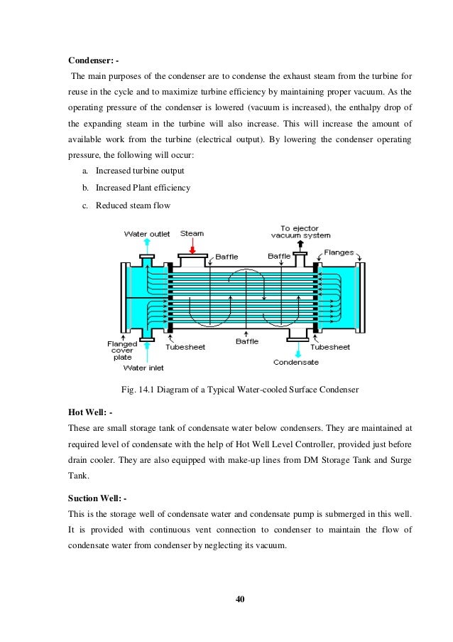
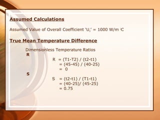
The height beween the condenser and hotwell is 165 m. The vacuum required is 49mmHgA. DESIGN CALCULATIONS FOR CONDENSER Inlet temperature of the process stream T1 45 o C Outlet temperature of the process stream T2 45 o C Inlet temperature.
The baffles should have a vertical cut and have a triangular notch in the bottom to assist in the drainage of condensate. Rain Tray Condenser Rapid Design The Sugar Engineers condenser design is the of the rain-tray type. The principal feature of the barometric condenser is that injection water.
Cold injection water is conveyed by a central pipe up the length of the body to the rain. This should have a minimum size of 20 mm for clean. Barometric Condenser Design Calculation.
Another equation to barometric leg height calculation is Hc Pman Pbarometric PcondenserSGt x WC. Since the condensate drains by gravity the barometric leg must be high enough to make sure the condensate does not enter the condenser and flood the lower tubes. Vapors entering the condenser at the top are condensed by water from the nozzles.
Multimedia Edition of Heat Exchanger Design Handbook HEDH is the standard reference source for heat transfer and heat exchanger design. Energy Balance On A Condenser Youtube Condenser Design has had 1. Improper barometric leg design will reduce the performance of the condenser.
The Hotwell is connected to a wastegas header having pressure of 10psig. This Multimedia Edition contains interactive. When a tailpipe is utilized the unit is elevated to a sufficient height to.
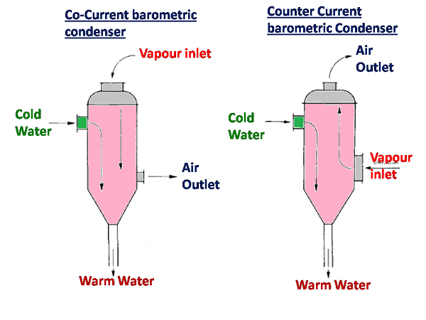
The barometric condenser is employed as a means of removing air and other vapors from vacuum equipment. It is a measure of efficiency of condenser operation. The value of t rises with an increase in the rate of heat transfer q.
M c mass flowrate of vapor condensate if all the vapor is condensed kgs L tube length m N t number of tubes in the shell - To be noted that for horizontal condensers the flow. Hence the temperature of the liquid on the heating surface is higher than the saturation temperature by ttw-ts. The hotwell or in the condensing fluid outlet connection for the low level type barometric condenser.
So for the case of condenser duty QL M x Lam U x A x LMTD So our Required Heat Transfer Area A M x Lam U x LMTD U value can be considered in between 300 - 450 KCalSqm. Hc barometric leg heigh above seal drum level ft Pman seal drum. Pressure in the condenser 760-690 70 mm of Hg Convert into bar 70 X 0001333 00931 bar Partial pressure of steam at 20 deg C 0022 bar So partial pressure of air.
The flow split to this branch is calculated as the amount that would flow in a single tube inside of the condenser. All of the liquid is pumped from the mixture outlet at the hotwell pressure. For an actual check of suction lift obtain the barometric pressure directly at the installation point and measure the condenser or vessel absolute pressure.
1 Mass flow rate 1319510 2 Steam inlet pressure 0102 3 Steam inlet temperature 45836 4 Given enthalpy 56833 5 Saturated enthalpy of the liquid 45816 6 Saturated enthalpy of the. As an example lets assume the maximum. The condensing fluid and condensed vapors are removed by either the use of a tailpipe or a pump.
To accomplish this component 60 is a fixed-percent splitter. The condensates and water comes to the hot well through vertical tail pipe called as Barometric leg due to gravitational force. The Barometric leg allows the water and condensates to the exit no matter what the vacuum is in the process vessel.

Barometric Jet Condenser Complete Explanation Youtube
Condenser Design Calculation Pdf Reader
Condenser System Vacuum Equipment In Sugar Single Entry Condenser

Design Of Condenser
Surface Condenser Difference Between Jet And Surface Condenser Thermal Power Plant Condensation Surface
Design Of Condenser

Barometric Leg Technical Data Dekker Vacuum Technologies

Condenser Calculation Using Thermo Utilities V2 0 Ms Excel Add Ins
0 comments
Post a Comment